Terminology
Anticline
An anticline is a convex fold in rocks or sediments where the oldest layers are in the core of the fold (figure 6B), compare syncline.
Aquifer
An aquifer is an underground water-bearing porous and permeable layer often of sedimentary origin, such as sandstone or limestone (sedimentary rocks) or gravel or sand (sediments). Volcanic rocks or crystalline rocks with fractures may also form aquifers. See also saline aquifer. The aquifer can be either open or closed to some degree in terms of confining faults or stratigraphy (figure 1).
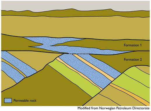
Figure 1. Example of an aquifer, which in this case consists of porous layers from two formations with connectivity.
Bentonitic
A bentonitic rock is rich in absorbent bentonite clay minerals, such as smectites, which have good properties for sealing, due to swelling properties.
Caprock
See Seal.
Carbonates
Carbonates are rocks (limestone) or minerals containing carbonic acid (CO3) together with a base. For example calcium (Ca), forming calcium carbonate, CaCO3. Most carbonate rocks form from biogenic processes.
CO2 plume
The dispersing volume of CO2 in the geological formation. Definition from the EU CCS Directive, 2009.
CO2 storage maturity
Maturity in connection with CO2 storage is used as an informal term to indicate how close a potential site is to utilisation. This is a combination of certainty in storage capacity, site integrity and safety aspects, which all depend on the available knowledge.
CO2 stream
A flow of substances that results from CO2 capture processes. Definition from the EU CCS Directive, 2009.
CO2 trapping
When CO2 is injected into a reservoir rock various trapping mechanismes can take place (figure 2 and 3).
- Structural and stratigraphic trapping (see Trap, figure 6) occurs when the buoyant CO2 is prevented from moving to the surface, because the CO2 is caught below low permeable rock layers.
- Residual trapping, is a physical trapping of CO2 within the pore space of the rock due to capillary forces.
- Solubility trapping describes CO2 dissolved into the formation fluids.
- Mineral trapping occurs where CO2 reacts with the reservoir rock and/or formation fluids to form carbonate minerals.
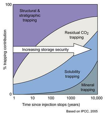
Figure 2. A possible relationship between different trapping mechanisms and time. The relative importance of the different trapping mechanisms can change depending on type of aquifer (closure, open dipping, homogenous/heterogeneous etc.).
Depression
In geological terms, a depression is a sunken landform with a lower position than surrounding areas.
Diagenesis
Diagenesis is the sum of changes in a sediment after deposition. Porosity is reduced due to compaction (weight of overlying sediments), dissolution of instable minerals and precipitation of new, stable minerals in the pore spaces. The transition from sand to sandstone involves diagenetic processes.
Exploration
The assessment of potential storage complexes for the purposes of geologically storing CO2 by means of activities intruding into the subsurface, such as drilling and seismic surveys, to obtain geological information about strata in the potential storage complex and, as appropriate, carrying out injection tests in order to characterise the storage site. Definition from the EU CCS Directive, 2009.
Facies
A facies is the sum of features characterising a specific rock. Sedimentary facies reflect specific depositional processes in a certain environment. Facies are also defined for metamorphic and volcanic rocks.
Fault
A fault is a fracture, or fracture zone, in a body of rock along which block-movement and displacement has taken place (figure 6A and C). Faults may subdivide a reservoir.
Fault confined
A body of rock confined by faults resulting in a complete or partly isolated rock unit (figure 6C).
Formation
A formation, or geological formation, is the fundamental unit of lithostratigraphy. A formation consists of a number of rock layers with a distinct lithology or facies sequence and must be mappable within a region. Formations can vary in thickness from a few meters to several thousand meters. Formations can form part of a group, or may be subdivided into members.
Formation fluids
The naturally occurring fluids in a subsurface rock. These will in most cases be saline water (also termed pore water or brine, Fig. 3), but the term also covers the occurrence of oil and gas.
Geological setting
A geological setting is a physical and environmental frame for deposition.
Geological storage of CO2
Injection accompanied by storage of CO2 streams in underground geological formations (figure 3). Definition from the EU CCS Directive, 2009.
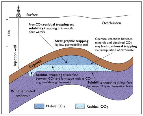
Figure 3. Overview of a conceptual storage site and different trapping mechanisms. The buoyant CO2 will move towards lower pressure (the surface).
Geological structure
A geological structure, is a physical subsurface feature that has been defined geologically or geophysically, and contains physically trapped fluids. Examples include anticlines, fault blocks and stratigraphic traps (figure 10). Definition from the EU CCS Guidance Document, 2009.
Geological time scale
Please see website for the International Commission on Stratigraphy. The time scale is revised following decisions by the Commission.
http://www.stratigraphy.org/index.php/ics-chart-timescale
Geothermal gradient
The heat gradient measured from the surface and downwards through the subsurface. Average value is 25-30 ◦C per km, but can be higher in volcanic areas.
Graben/Halfgraben
A graben is a structural term describing a downthrown block bounded by two parallel faults.
A halfgraben has an asymmetric subsidence, and the strata dip toward the longest of the bounding faults.
Heterogeneous rock sequence
A heterogeneous rock succession consisting of alternating layers of rocks with different composition and/or grain size. Depending on the scale (cm to tens of metres) and mode of formation (depositional environment for sedimentary rocks) the heterogeneous succession may belong to one facies or one formation.
Homogeneous rock sequence
A homogeneous rock sequence has only minor differences in composition and/or grain size throughout the sequence.
Hydraulic connection
Connected pore spaces, which allow flow of fluids (see also permeability).
Hydraulic unit
A hydraulically connected pore space where pressure communication can be measured by technical means and which is bordered by flow barriers, such as faults, salt domes, lithological boundaries, or by the wedging out or outcropping of the formation. Definition from the EU CCS Directive, 2009.
Injectivity
A measure of the CO2 injection rate into a reservoir and thus how fast the CO2 migrates away from the well. It is defined as the product of the reservoir permeability and thickness, unites in Darcy metre (Dm). (See also well injectivity index)
Lithology
Lithology is the physical characteristic of a rock, i.e. mineral composition, grain size, structure, texture, colour etc.
Lithostatic pressure
The pressure due to the weight of the entire overburden (fluid plus matrix). The lithostatic pressure gradient is 22-26 MPa (220-260 bars) per km.
Leakage
Any release of CO2 from the storage complex.Definition from the EU CCS Directive, 2009.
Migration
The movement of CO2 within the storage complex. Definition from the EU CCS Directive, 2009.
Net/Gross ratio (N/G)
Is an estimate of the storage capacity of a formation, i.e. the volume of reservoir rock suitable for CO2 storage relative to the bulk volume of the storage formation. The ratio is found by analysing well log curves and apply cut-off values separating the reservoir part (net) from the bulk volume (gross).
Platform
A platform is a coherent area covered with relatively flat sedimentary strata directly overlying the crystalline basement.
Porosity
Porosity is a measure of how much of a rock is open space (filled by air or formation fluids). This space can be between grains or within cracks or cavities of the rock. Values are given as a percentage or fraction.
Permeability
Permeability is a measure of the ability of a fluid to flow through a porous rock. Measured in milli-Darcy (mD) or Darcy (D).
Reservoir
A reservoir is a large subsurface porous layer containing fluid or gas, in many cases this will be porous sandstone or limestone.
Saline Aquifer
An aquifer where the salinity of the formation water is above 3% making it unsuitable as potable water.
Seal (Caprock)
A seal is a layer with low permeability, which prevents the fluid or gas from migrating towards the surface. This is often called the caprock, and is often a claystone.
Sedimentary basin
A sedimentary basin is an area at the earth's surface, which accumulated and preserved sediments due to a higher subsidence. A sedimentary basin has definable margins and the scale of basins varies greatly (from tens to thousands of km).
Sediment
Sediments are divided into clastic -, biogenic, and chemical sediments. Clastic sediments consist of particles formed by weathering and erosion of older rock material. The particles are subsequently transported by wind, water or ice to be deposited and form sediments (such as sand) or sedimentary rock (sandstone). In biogenic sediments the particles form by biological processes, fragments of shells, tests, and plant remains. Limestone is the most important group of biogenic sediments. Chemical sediments, such as evaporites, form by chemical processes. Classification of sedimentary rocks can be based on mineralogy and grain size.
| Clay | Silt | Fine sand | Medium sand | Coarse sand | Gravel |
|---|---|---|---|---|---|
| < 0.002 mm | 0.06─0.002 mm | 0.2─0.06 mm | 0.6─0.2 mm | 2.0─0.6 mm | > 2 mm |
Seismic survey
A seismic survey is a method of investigating the geometry of subsurface layers by the use of acoustic signals.
Spill point
In relation to traps a spill point is the location were the trap content will leak from, when the trap is filled up.
Storage capacity
The available pore volume for CO2 storage in a storage formation, storage unit or trap.
Storage capacity calculation – static
Static CO2 storage capacity assessments can be evaluated on different levels from basin scale and down to a single trap. Several CO2 storage projects have attempted to assess the geological storage potential and no standard methodology exist yet, but most projects agree on calculations based on volume of the storage formation, storage unit or trap, porosity, volume of the CO2 at reservoir conditions and a storage efficiency factor. The current status for harmonisation and recommendations of CO2 storage assessments are summarised in the International Energy Agency workshop report from 2013 “Methods to assess geological CO2 storage capacity: status and best practice”.
The CO2 storage capacity calculations in the Nordic CO2 Storage Atlas follow the EU GeoCapacity methodology (Vangkilde-Pedersen 2009). The calculation methodology is valid for sedimentary storage aquifers, storage units and traps.
Theoretical CO2 storage capacity
TH_MCO2 = V × N/G × f × rCO2r
- TH_MCO2
- theoretical storage capacity
- V
- volume of trap or regional aquifer
- N/G
- average net/gross ratio
- f
- average reservoir porosity
- CO2r
- CO2 density at reservoir conditions
Effective CO2 storage capacity
EFF_MCO2 = V × N/G × f × rCO2r × Seff
- EFF_MCO2
- effective storage capacity
- V
- volume of trap or regional aquifer
- N/G
- average net/gross ratio
- f
- average reservoir porosity
- CO2r
- CO2 density at reservoir conditions
- Seff
- storage efficiency
For the Danish and Swedish storage sites Seff is based on GeoCapacity “Rule-of-thumb” approach (Figure 4).
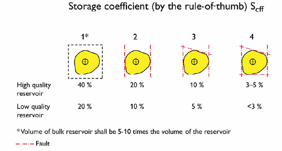
Figure 4. Illustration of the “Rule-of-thumb” used in EU GeoCapacity (Vangkilde-Pedersen 2009).
The Norwegian Seff values are taken from “CO2 Storage Atlas – Norwegian Continental Shelf” by the Norwegian Petroleum directorate, 2014 (Halland et al. 2014).
Storage capacity calculation – dynamic
Dynamic capacity calculations are based on reservoir simulations of CO2 injection.
Storage efficiency factor
Is the fraction of the accessible pore volume that can be occupied by CO2.
Storage site
A defined volume within a geological formation used for the geological storage of CO2 and associated surface and injection facilities.Definition from the EU CCS Directive, 2009.
Storage unit
A part of a formation where CO2 can be stored (the porous and permeable parts). A formation can have several storage units and a storage unit can have several traps. Storage units are without hydraulic connection and can be separated by faults, facies variations, diagenesis etc. See also hydraulic unit. The term is also used for a defined national part of a storage aquifer e.g. for Sweden.
Strata
Strata are the latin word for layers. The layers within a sedimentary succession are distinguished from other layers by specific characteristics.
Stratigraphic trap
A stratigraphic trap is formed as a result of lateral and vertical variations in the porosity/permeability of the reservoir rock with respect to the surrounding bedrocks. See Trap and figure 6.
Stratigraphy
In geology, stratigraphy is the study of rock layers (strata) and their mutual relationships with respect to age, fossil content, lithology and depositional environment. Subfields in stratigraphy are lithostratigraphy, based on lithology, and biostratigraphy, based on flora and fauna, chronostratigraphy and sequence stratigraphy.
Structural trap
A structural trap is formed as a result of deformation of the rock layers. See Traps and figure 6.
Super critical CO2
CO2 becomes supercritical at a pressure around 73 bar and a temperature of approximatly 31 ◦C where the volume of CO2 will have decreased to about 0.3% of the volume at surface temperature and pressure conditions. Depending on the geothermal gradient and lithostatic pressure these temperature and pressure conditions are present at about 800 meter depth. In supercritical state CO2 will be a fluid behaving like a gas (figure 5).
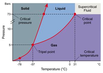
Figure 5. Phase diagram for CO2.
Syneclise
A syneclise is a large depression formed by slow and steady subsidence on a continental platform.
Trap
A trap is a geometric arrangement of rocks that permits significant accumulation of fluid or gas in the subsurface. A trap includes a reservoir rock and a seal that impede or prevent migration out of the reservoir. Traps are divided into structural trap and stratigraphic traps or a combination of both (figure 6).
Volcanic rocks
Volcanic rocks are formed in a magma chamber underground and erupted to the surface from a volcano. Usually volcanic rocks are very fine-grained crystalline or glassy igneous rock resulting from volcanic action at or near the Earth’s surface either ejected explosively or extruded as lava (e.g. basalt).
Well injectivity index
Well injectivity index is defined as the injection rate divided by pressure drop from the well into the reservoir, i.e. II= q/(Pw-Pr)=(2πkh)/(μB(ln(re/rw)).
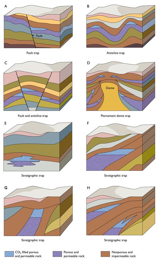
Figure 6. Illustrating structural (A – D) and stratigraphic traps (E – H).
References
DIRECTIVE 2009/31/EC OF THE EUROPEAN PARLIAMENT AND OF THE COUNCIL of 23 April 2009 on the geological storage of carbon dioxide and amending Council Directive 85/337/EEC, European Parliament and Council Directives 2000/60/EC, 2001/80/EC, 2004/35/EC, 2006/12/EC, 2008/1/EC and Regulation (EC) No 1013/2006
DIRECTIVE 2009/31/EC OF THE EUROPEAN PARLIAMENT AND OF THE COUNCIL (PDF)Halland EK, Mujezinovic J, Riis F (eds). CO2 Storage Atlas – Norwegian Continental Shelf. The Norwegian Petroleum Directorate. 2014. 163 pp.
Compiled CO2 atlas for the Norwegian Continental ShelfImplementation of Directive 2009/31/EC on the Geological Storage of Carbon Dioxide, Guidance Document 2, Characterisation of the Storage Complex, CO2 Stream Composition, Monitoring and Corrective Measures
Implementation of Directive 2009/31/EC on the Geological Storage of Carbon Dioxide (PDF)International Energy Agency workshop report from 2013 “Methods to assess geological CO2 storage capacity: status and best practice”.
Methods to assess geologic CO2 storage capacity: status and best practice (PDF)Metz, B., Davidson, O., Coninck, H., Loos, M., Meyer, L. (eds) 2005. IPCC Special Report on Carbon Dioxide Capture and Storage. Cambridge University Press, 443 pp.
CARBON DIOXIDE CAPTURE AND STORAGE (PDF)Vangkilde-Pedersen T (Ed). Capacity standards and site selection criteria. EU GeoCapacity report D26. 2009.
Project no. SES6-518318 EU GeoCapacity (PDF)